TM 55-4920-413-13&P
4-13. IDSL Test Set Circuits.
a. Lamp Circuit.
(1) Set INPUT POWER switch to SIM ONLY and test
equipment power to ON.
(2) Observe that the 115vac indicator lamp lights is on.
If not, perform Troubleshooting Table 4-5.
(3) Observe that the 28vdc indicator lamplights are on.
If not, perform Troubleshooting Table 4-5.
(4) Press LAMP TEST Switch all warning lamps will
light. If not, perform Troubleshooting Table 4-5.
(5) Connect 5vdc power supply (current limited to 25 ma)
between J1 connector pins U, V (+) and EE (-).
(6) LAMP SUPPLY OVERLOAD NO. 1 warning lamp
will go ON. Set LAMP SUPPLY OVERLOAD switch to left,
lamp will go OFF. If not, see Troubleshooting Table 4-5.
(7) Disconnect dc power supply from J1 connector pins
and connect to J2 connector pins U, V (+) and EE (-).
(8) LAMP SUPPLY OVERLOAD NO. 2 warning lamp
will go ON. Set LAMP SUPPLY OVERLOAD switch to right,
lamp will go OFF. If not, see Troubleshooting Table 4-5.
(9) Disconnect dc power supply from J2 connector.
(10) INTEGRAL LIGHTING INT/EXT circuit. Connec-
tor digital voltmeter between J1 pin HH (LOW) and FF(HI).
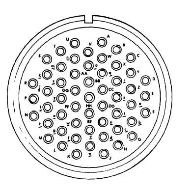
Refer to Figure 4-2 for pin locations.
(11) Observe that ON-OFF-SIM ONLY switch is set to
SIM ONLY and INTEGRAL LIGHTING is set to INT digi-
tal voltmeter will indicate between 4.0 and 6.0 vac, If not, per-
form Troubleshooting Table 4-5.
Figure 4-2. Signal Data Converter Connectors NO 1 and NO 2
4-6


