TM 5-2420-224-20-2
REAR AXLE TORSION BAR REPLACEMENT
This task covers:
a. Removal b. Installation
I N I T I A L S E T UP
Tools and Special Equipment:
Shop Equipment, SC 4910-95-CL-A74
TooI Kit, SC 5180-90-CL-N26
Equipment Condition:
Reference
Condition Description
Page 4-335
Rear Wheel Assemblies
Materials/Parts:
Removed
Nut, Lock (2)
General Safety Instructions:
Nut, Lock (2)
Pin, Cotter (2)
W A R N I N G
Personnel Required: (2)
• M a k e s u r e r e a r a x l e i s
properly supported with jack
References:
s t a n d s . F a i l u r e t o d o so
LO 5-2420-224-12
could result in serious injury
to personnel.
R E M O V A L
NOTE
Procedure is the same
sides except as noted.
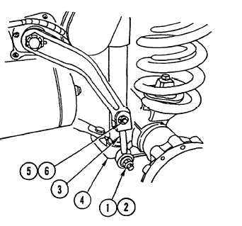
1.
REMOVE lock NUT (1)
2.
for both
and BACK out
SCREW (2) far enough to RELEASE
connecting LINK (3) from shock mount (4).
DISCARD lock NUT.
REMOVE lock nut (5), screw (6), and
connecting LINK (3). DISCARD lock NUT.
4-378

