TM 5-2420-224-20-2
VALVE ADJUSTMENT
This task covers: Adjustment
Tools and Special Equipment:
Equipment Condition:
TooI Kit, SC 5180-90-CL-N26
Reference
Condition Description
Page 4-3
Valve Cover Removed
1.
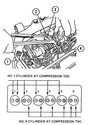
Rotate crankshaft to right until rocker arms of
No. 6 cylinder overlap. No. 1 cylinder will now
be at Top Dead Center (TDC).
C A U T I O N
Do not make valve adjustments
u n t i l e n g i n e h a s c o o l e d t o
below 122° F (50° C) to prevent
damage to equipment.
2.
Using feeler gage, check valve clearance.
Clearance for intake valves 2, 3, and 7 is
0.008 in. (0.20 mm). Clearance for exhaust
valves 1, 5, and 9 is 0.012 in. (0.30 mm).
3.
If adjustment is required, loosen nut (1) and
insert feeler gage between rocker arm (2) and
pad (3). Turn adjusting screw (4) until rocker
arm just touches feeler gage. Tighten nut (1)
and recheck clearance.
4.
Rotate crankshaft to right until rocker arms of
No. 1 cylinder overlap. No. 6 cylinder will now
be at TDC.
5.
Repeat steps 2 and 3 for intake valves 6, 10,
and 11 and exhaust valves 4, 8, and 12.
NOTE
Follow-on Maintenance:
Install valve cover (page 4-3).
4-5


