TM 11-7440-232-12/NAVELEX 0967-LP-275-5010
CHAPTER 2
OPERATING INSTRUCTIONS
Section I. DESCRIPTION AND USE OF OPERATOR'S CONTROLS AND INDICATORS
2-1. GENERAL
a. As the operator of the digital data modem, you will be concerned with four types of controls and two indicators.
CONTROLS
INDICATORS
Transmit And Receive Mode
Power
Bit Rate
Errors
Alarm
Power Supply
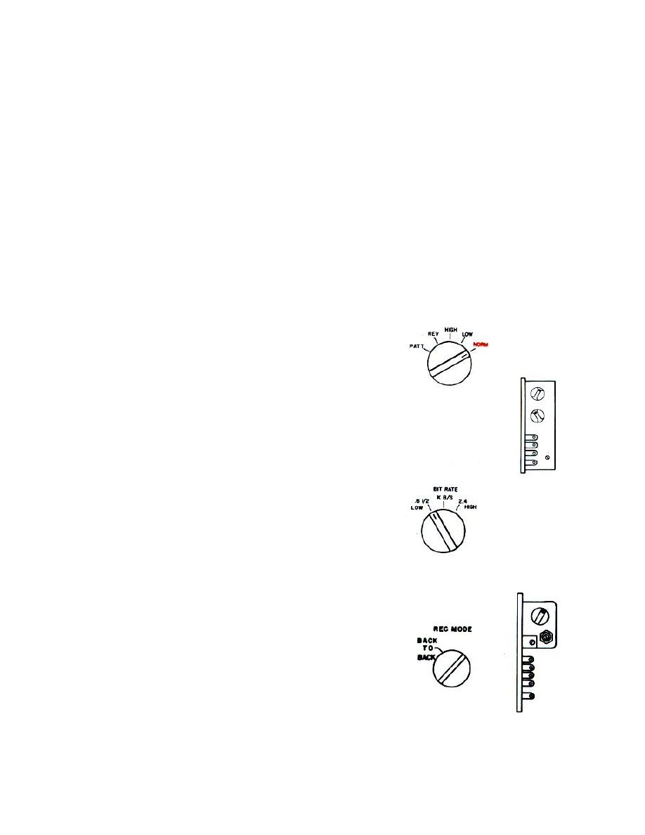
b. Location of operating controls and indicators on modules is shown on a decal on the inside of the Modem shelf
front cover.
2-2. CONTROLS
TRANS MODE Switch
Five position rotary switch
During operation, switch position NORM allows
transmission of input digital data.
During organizational maintenance and testing:
LOW-1200 Hz signal is applied to transmit line
HIGH-2400 Hz signal is applied to transmit line
REV-test pattern generator produces a reversal
pattern of alternate ones and zeroes; and signal
appearing on transmit line resembles alternate
one and zero data input pattern for particular
data rate applied.
PATT-test pattern generator produces a random
data input which results in a random data output
on transmission line.
BIT RATE Switch
Two position rotary switch
During operation controls transmitted data rate
LOW-600/1200 bps
HIGH-2400 bps
LIMITER DISCRIMINATOR
REC MODE SWITCH
Two position rotary switch
During operation switch position allows reception
of received digital data
2-1


