TM 11-7440-232-12/NAVELEX 0967-LP-275-5010
1-16. RECEIVE
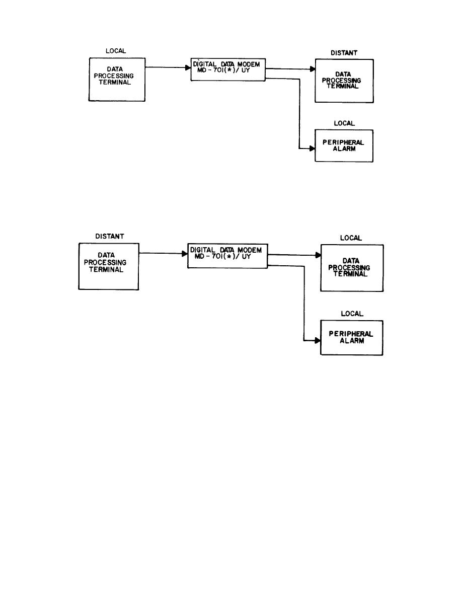
a. Receive branch contains five modules: a receiver line filter, adjustable equalizer, limiter discriminator, decoder
error detector, and receiver clock. The receive branch converts signals on the receive line to serial-by-bit NRZ binary
signals to drive the receiving data processor. The decoder error detector provides an error indicator at the front cover
and supplies error output signals to alarm equipment.
b. REC MODE switch on limiter discriminator module is used for selecting the mode of reception and during the
mission is set to NORM. The other position, BACK-TO-BACK, is used during modem maintenance. BIT RATE switch on
decoder error detector module and the BIT RATE switch on the digital receiver clock are used for selecting the operating
bit rate of the receive branch.
1-17. ALARMS
The Data Carrier Alarm module provides individual alarm outputs if trouble occurs in any of the monitored signal
paths: transmit data, transmit carrier, receive carrier, and receive data signals. This type of alarm output provides a fail-
safe feature, in that, failure of the circuit being monitored, failure of the alarm circuit, or failure within the entire digital
data modem will always produce an alarm output. ALARM CUTOFF switch when set to NORM is used for providing an
alarm signal and when set to CUTOFF for cancelling an alarm signal.
1-26


