TM 11-7025-234-23
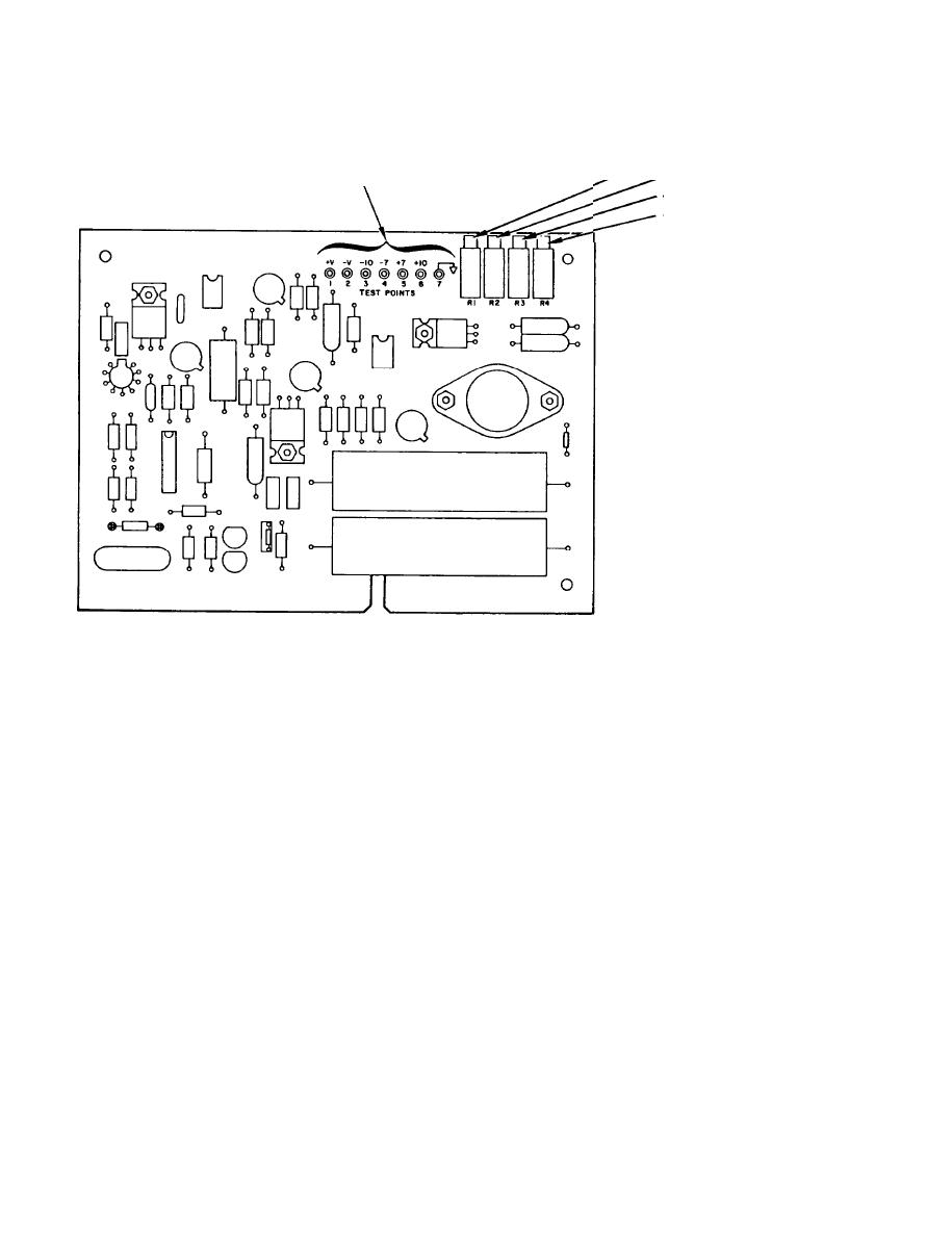
+10
VDC
TEST POINTS
+7
VOLTAGE
VDC
ADJUSTMENT
VDC
-7
-l0
VDC
NOTE
IF THE POWER SUPPLY
REGULATOR BOARD (Al)
IS REPLACED, THE +7
AND -7 AND THE +10
AND -10 VOLT OUTPUTS
MUST BE ADJUSTED TO
WITHIN lOmV.
Power Supply Regulator Board (Al)
b. Control Board (A4). Data, commands, and signals are received by the control
board. Data is handled in or out. This board contains the logic circuitry for the
train function (synchronized between transmitter and receiver). It also contains
the clock timing selector, rate/mode, and configuration control.
Transmitter Board (A7). Data to be transmitted consists of synchronous
(timed) digital Information.
To make it less subject to losses on its line, the
digital signal is coded, scrambled, modulated and digital-to-analog converted.
This data is transmitted at either a 1200, 1600, or 2400 baud rate. Data from the
transmitter then goes to the 1/0 board and out on pins 7 and 8 of J5.
2-8. RECEIVING FUNCTION
Data from a transmitting V.29 modem is received by the remote unit receiver board
(A5). It is then sent through the equalizer (A6), control (A4), and interface (A3)
boards.
a. Receiver Board (A5). Incoming audio signals from the remote modem are
received at terminals four and five of TB-1 or terminals nine and ten of J5. This
input is AGC amplified, analog-to-digital converted and demodulated. It is then
equalized, decoded, descrambled, and sent to the control board. The receiver also
recovers the carrier and timing.
2-8


