TM 11-7025-234-23
(1) Shutdown Feature. The jumpers which cause the power supply to shut down
upon removal of boards A3 or A4 are on EF and GH (fig. 1-7). These jumpers are
placed on AB and CD to override the shut down feature for troubleshooting.
However, they should be returned to EF and GH when the modem assembly is placed
back into normal operation.
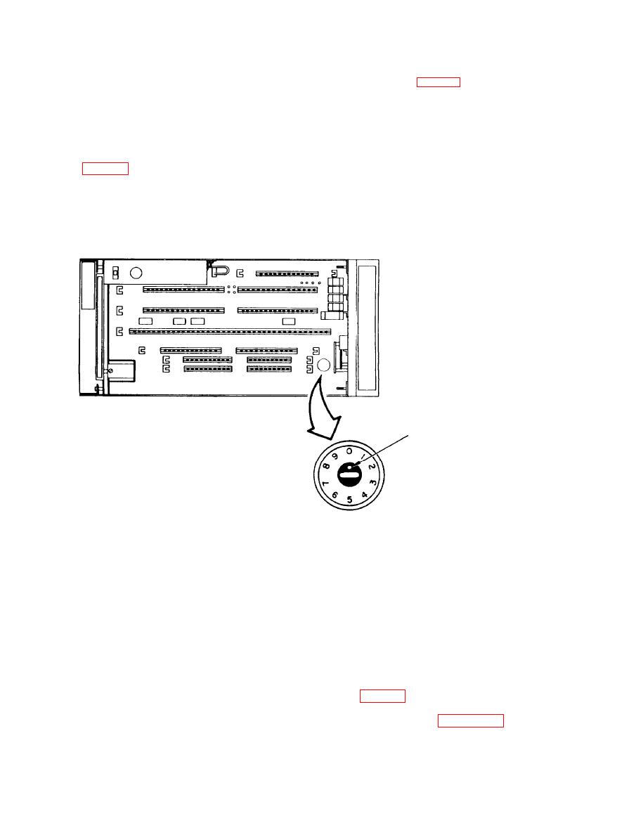
(2) Transmit Output Level Switch. The transmitter output signal level is
controlled by a ten position screwdriver-adjustable switch located near board A7
WHITE DOT
INDICATES
POSITION
OF SWITCH
SCREWDRIVER
ADJUSTABLE
1O-POSITION
SELECTOR SWITCH
Transmit Output Level Switch
(3) Ground Jumper. A ground jumper (fig. 1-7) is provided to connect
protective ground
pin 1 to signal ground pin 7 J1 thru J4) to signal ground (AB
ground or Signal to Chassis Ground). The other terminal is used only when a ground
fault is suspected or when ground has an unsatisfactory noise level.
1-11


