C1, TM 11-5805-424-15/NAVSHIPS 0967-220-9010/TO 31W2-2G-41
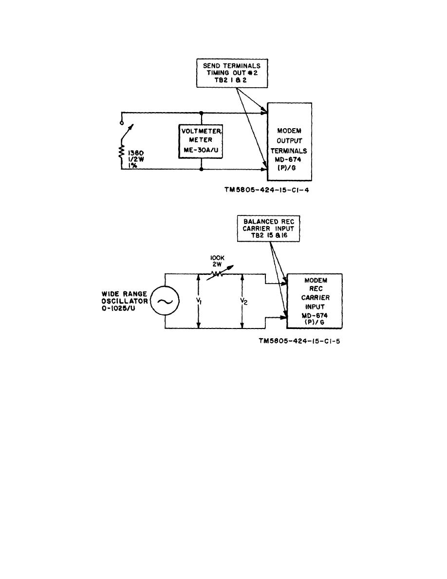
Figure 8.1-3. Connections for output impedance tests.
Figure 8.1-4. Connections for input impedance tests.
8.1-7. Input Impedance Tests
(6) Measure the voltage (V2); it must be
The purpose of the input impedance tests is to
greater than 0.5 volt rms.
check to see that input impedances are 600 ohms and
b. 600-Ohm Termination.
50,000 ohms by performing the following procedures:
(1) Operate the POWER switch to ON.
a. 50,000-Ohm Terminator.
(2) Operate the 600-ohm termination switch
(1) Connect the equipment as shown in figure
to out and repeat a(5) above.
8.1-4.
(3) Set the value of R to make the voltage
(2) Operate the POWER switch to ON.
(V2) exactly one-half that of V1.
(3) Operate the 600-ohm termination switch
(4) Measure the value of R; it must be 600
to out.
ohms 10 percent.
(4) Set the value of R to 50,000 ohms.
(5) Repeat the procedures given in a above
(5) Set the SG-15/PCM to an output level of
and (1) through (4) above using 300 hz
1 volt rms at 1,000 hz.
and 3,400 hz.
8.1-4


