TM 11-5805-424-15/NAVSHIPS 0967-220-9010/TO 31W2-2G-41
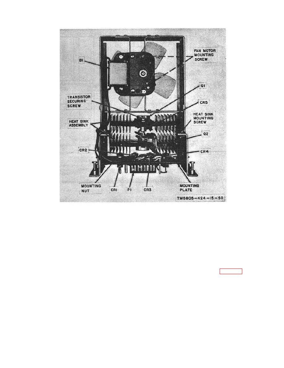
Figure 6-18. Power supply submodule, component location diagram.
dicator lamp should be extinguished, and
the reversals test pattern should be
(10) Depress the TALK REQUEST RESET
observed on the DSS-205A.
pushbutton. The ALARM indicator lamp
should be lighted and the TALK
(8)
Remove the patch plug from the ORDER
REQUEST indicator lamp should be
WIRE SEND test jack on the front panel.
extinguished.
The ALARM indicator lamp should be
(11) Check for bit-timing signals at the four
lighted, and the DSS-205A should indicate
a steady mark.
timing output terminals at the rear of the
MD-674(P)/G (fig.
2-2) with an
(9)
Depress the TALK REQUEST pushbutton
oscilloscope. Bit-'timing signals should be
on the MD-674 (P)/G front panel. The
present at all four terminals at all times
ALARM indicator lamp should be
during the operational tests described
extinguished, and then the TALK
above.
REQUEST indicator lamp should be
lighted.
6-21


