TM 5-2420-224-20-2
A L L W H E E L D R I V E C O N T R O L C Y L I N D E R R E P L A C E M E N T A N D
A D J U S T M E N T
This task covers:
a. Removal b Installation c. Adjustment
I N I T I A L S E T U P
Tools and Special Equipment:
TOOI Kit, SC 5180-90 -CL-N26
Materials/Parts:
Packing (3)
Equipment Condition:
Reference
Condition Description
Page 4-418
Cab Tilted
Page 2-23
Air Pressure Relieved
General Safety Instructions:
W A R N I N G
D o n o t d i s c o n n e c t a n y a i r
system lines unless all wheel
drive selector switch is in two
w h e e l d r i v e a n d a i r s y s t em
pressure is relieved. To do so
c o u l d r e s u l t i n i n j u r y t o
personnel.
R E M O V A L
NOTE
Tag lines prior to disconnecting to
aid in connecting.
1.
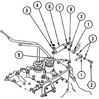
DISCONNECT two air HOSES (1) by
REMOVING fluid passage BOLT (2) and three
packings (3). DISCARD PACKINGS.
2.
REMOVE retaining ring (4), washer (5), and
CYLINDER (6).
3.
REMOVE CLIP (7) and DISCONNECT ball
RETAINER (8) from pivot ball (9).
I N S T A L L A T I O N
1.
INSTALL CYLINDER (6), washer (5), and
retaining ring (4).
2.
C O N N E C T t w o a i r H O S E S ( 1 ) by
INSTALLING three new packings (3) and fluid
passage BOLT (2).
4-243


