TM 11-7440-232-12 /NAVELEX 0967-LP-275-5010
POWER SUPPLY
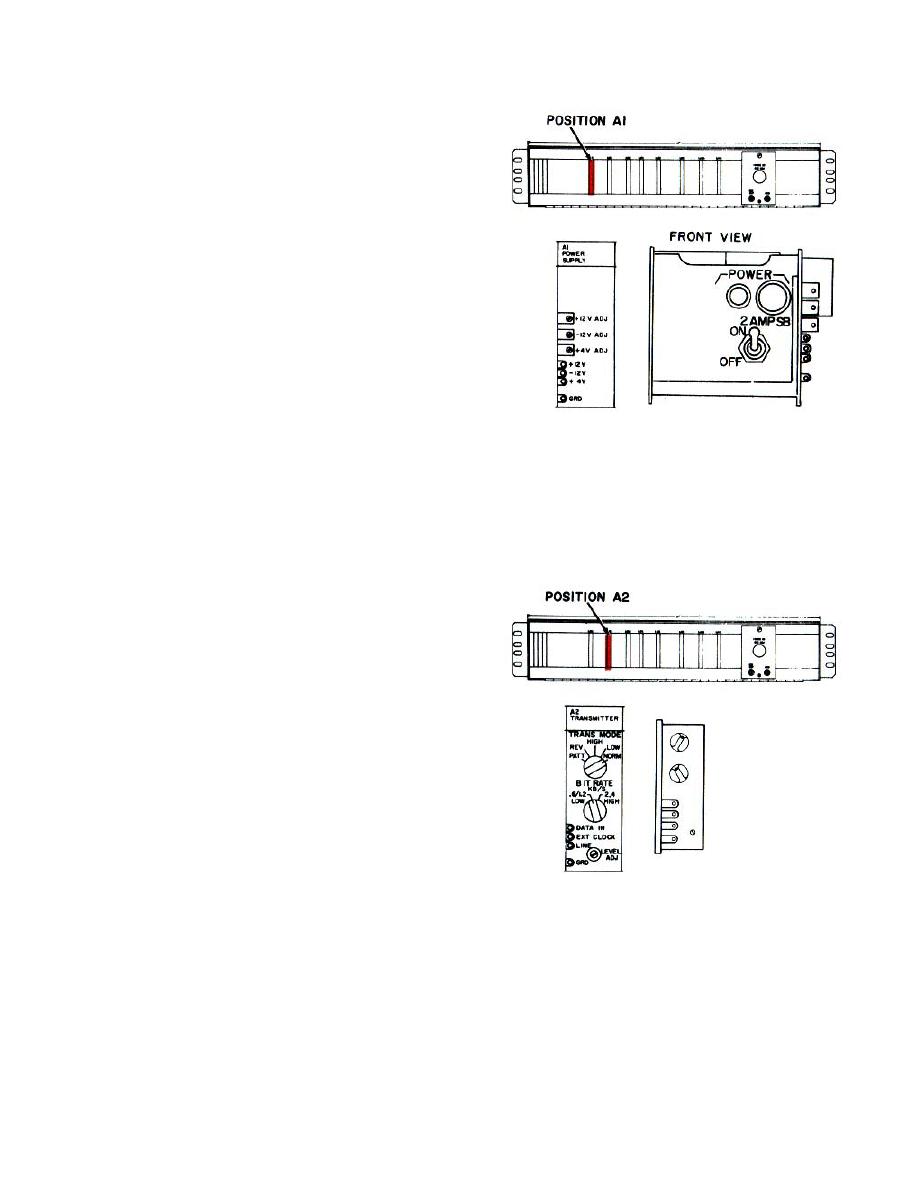
Power supply (PIN 900-44751-01) consists of a
chassis and a printed circuit card which plug into a jack
in the modem shelf. On the front of the chassis is an
on-off switch, pilot lamp, and ac line fuse. On the PCC
module are three potentiometers and three test jacks
which are used for adjusting the output voltages.
The 01 Option provides regulated +12, +4, and
-12 volts from an ac source. The 02 option provides the
same outputs as the 01 option, plus an alarm contact
closure if any of the supply voltages fail.
The power supply supplies power to all the
modules. The power supply has one operable POWER
switch and one POWER indicator.
DIGITAL DATA TRANSMITTER
Digital Data Transmitter (PIN 900-44752-01)
consists of a printed circuit module which plugs into the
modem shelf. All operating controls and test pin jacks
are on the front panel. The operating speed of the
transmitter is determined by the two position BIT RATE
switch on the front panel.
The digital data transmitter accepts serial
binary data at 1200 or 2400 bits per second and an
accompanying clock signal, and produces a
synchronous fm output for transmission over a vf path.
It supplies a square wave output at the desired bit rate
to the transmitter clock. It, also, contains a generator
that provides test signals for checking system operation.
The test pattern generator facilitates system
alinement and maintenance, and eliminates the need for
other data generators. This circuit produces four types
of test signals that result in a transmitter output of
steady 1200 Hz, steady 2400 Hz, reversals (alternate
one and zeros), or a random one and zero pattern.
1-9


